Introduction
Recent reports of randomised trials (ABSORB II, ABSORB Japan and ABSORB China) have raised questions on the “non” non-inferiority of the acute and long-term performance of the Absorb bioresorbable scaffold (BRS) when compared to the XIENCE stent1,2 (both Abbott Vascular, Santa Clara, CA, USA). Furthermore, very late scaffold thrombosis has been perceived as a possible new unexpected “enemy”3,4 – unexpected because thrombosis occurred at a moment when the scaffold was expected to have disappeared.
The three main players in this new debate are: the patient/lesion, the device, and the interventionalist5. The selection of the patient/lesion might be inappropriate, the device may have inherent deficiencies and the operator may have used the device inappropriately. If the matter were not of paramount importance for the wellbeing of our patients and were not a topic that demands our utmost medical attention, we would have rephrased the title of a past editorial, “Who was thrombogenic, the device, the doctor…or the patient?”6,7.
The format of the present commentary is neither an editorial nor a review, but should be considered as the personal views of two clinical scientists who have been involved in the pioneering investigations of this device and have historical and current insights into the field8,9.
Lessons learned from the first-in-man ABSORB cohort A trial (the first iteration of Absorb)
In 2007, the six-month report of the first iteration of the Absorb BRS showed what we called at that time “late recoil” with an in-device late loss of 0.44 mm – “late recoil” that could have been more appropriately described as constrictive remodelling, due to a bioresorption process that was both too fast and too early, causing loss of mechanical integrity of the scaffold10.
This amount of early late loss (0.44 mm) was then considered clinically unacceptable. A second iteration of the device was developed by modifying certain manufacturing processes, the description of which is at present beyond the scope of what we are attempting to do here.
Sixteen patients from this first cohort (n=30) were investigated with IVUS, IVUS-VH, OCT and MSCT. These pioneering investigations provided a basic understanding of the technology and set the trend for clinical research in this pioneering phase8,11-13.
Nevertheless, we must emphasise that this first iteration with fast bioresorption had an excellent two-year follow-up. As stated in the conclusion of the article published in The Lancet in 2009, “two years after implantation, the scaffold was bioabsorbed, had vasomotion restored and restenosis prevented and was clinically safe, suggesting freedom from late thrombosis”14.
Lessons learned from the ABSORB cohort B trial (second iteration of Absorb)
The second-generation Absorb BRS was studied in 101 patients with two different serial imaging follow-ups, either at six and 24 months, or at 12 and 36 months. The mechanical integrity of the scaffold at six months was then fully preserved since there was no decrease in mean and minimal scaffold area and no sign of pharmacological vasomotion. However, in that cohort, John Ormiston et al described one patient who had an OCT-diagnosed disruption of the scaffold caused by excessive post-dilatation15,16. This clinical observation of the “elongation-at-break” concept (expansion of ≥0.7 mm for a nominal device of 3 mm) made the investigators more wary for future trials.
The first six-month assessment showed that the modified manufacturing process of the polymer and geometric changes in the polymer platform substantially improved the medium-term performance (in-device late loss of 0.19±0.18 mm) of the device16. In the 12-month cohort, the in-device late lumen loss amounted to 0.27±0.32 mm and, more importantly, there was no scaffold area loss although pharmacological vasomotion of the scaffold vessel was restored17.
We concluded that the performance of the second-generation Absorb BRS justified a randomised trial being carried out, with a comparator considered as the best-in-class metallic drug-eluting stent. By August 2010, the first randomised trial protocol was drafted and the first patient was randomised in November 201118.
Although the non-serial observations of cohort B showed no sign of scaffold area reduction at six months and recovered vasomotion at one year, serial observation at six months and two years showed that in-device late luminal loss increased from 0.16±0.18 mm to 0.27±0.20 mm. Struts were still recognisable on OCT at two years and a significant increase in scaffold area was documented19. The MACE rate was 6.8% without any scaffold thrombosis19.
The three-year follow-up showed stable luminal dimensions with an in-device late loss of 0.29±0.43 mm, a low restenosis rate of 6% and a MACE rate of 10% without any scaffold thrombosis20.
The five-year follow-up confirmed these results. When patients with a target lesion revascularisation were included (the worst scenario), the in-stent late loss was 0.32±0.48 mm21. In-scaffold and in-segment binary restenosis were 7.9% and 12.5%, respectively. At five years, struts were no longer discernible by OCT or IVUS. The overall five-year MACE rate was 11% without any thrombotic event.
Angiographic maximal lumen diameter (Dmax), the “poor man’s” sizing technique?
In the aftermath of the first-in-man studies (ABSORB A and B), a better understanding of the dimensional relationship between quantitative angiography, IVUS and OCT was achieved22. It was firmly established that the lumen dimensions obtained by QCA were smaller than those obtained using OCT, which in turn were smaller than the ones provided by IVUS. Nevertheless, the OCT measurements emerged as the gold standard since the precision and accuracy of the OCT measurements versus measurements performed on a plexiglass phantom were exceptional23.
Besides these quantitative considerations, some qualitative observations were made on the angiographic luminal contours as compared to the endoluminal assessment by OCT of the interaction of the scaffold with the vessel wall (e.g., malapposition, strut embedment, etc.).
Diameter function derived from QCA defined three non-ambiguous points: two maximal diameters – one proximal and one distal to the minimal lumen diameter of the lesion. Therefore, the operator had to estimate whether the landing zone of the scaffold would or would not be apposed in the proximal and/or distal Dmax.
Due to the tapering of the vessel, issues with scaffold implantation may be quite different in the proximal and distal ends of the scaffold: proximally, malapposition of struts is the more frequent issue; distally an oversized device with possible edge dissection is the more prevalent problem (Figure 1). Thus, the operator has to decide on a scaffold size and length that are compatible with the Dmax proximal and distal in order to avoid malapposition, dissection and mismatch altogether.
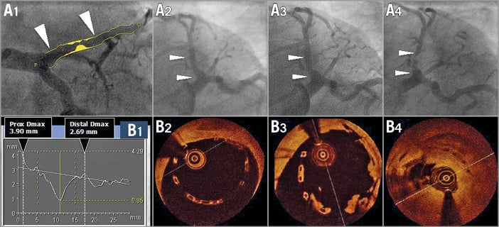
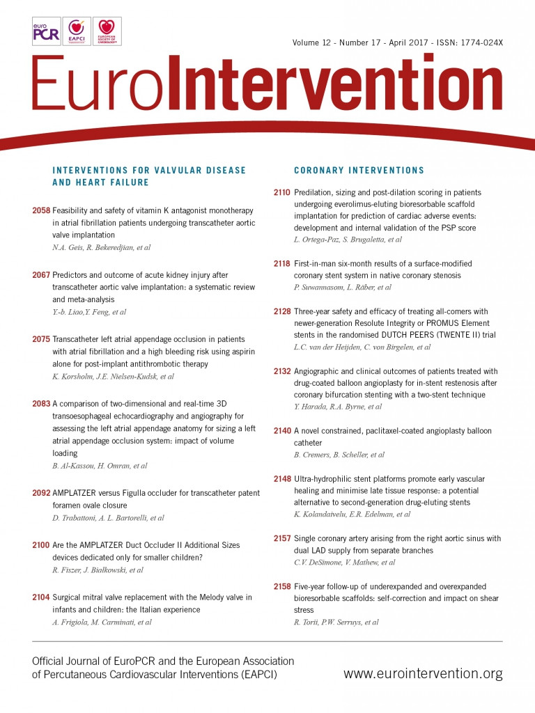
Figure 1. Assessment of maximal diameters by QCA (A1 and B1) and OCT imaging (B2-B4) post-procedure at six and at 18 months. A 3.0 mm scaffold was implanted in a proximal left anterior descending artery with a large proximal diameter (A1). The quantitative angiographic assessment demonstrated that the proximal maximum diameter of the vessel was 3.9 mm, whereas the distal maximum diameter was 2.69 mm (B1). After implantation of an Absorb BRS, the proximal part of the scaffold was malapposed by more than 0.5 mm. Post-dilatation was performed with a 3.5 mm balloon to correct the large malapposition; however, the scaffold still remained malapposed (A2 and B2). Further post-dilatation with a larger balloon (e.g., 4.0 mm) was not performed due to the risk of scaffold disruption. At six months (A3 and B3), struts were still malapposed and lumps of “tissue” were attached to the malapposed struts. One year later (A4 and B4), the patient presented with unstable angina and had a subtotal stenosis with a possible thrombotic component19.
In their article in this issue of the journal, Ortega-Paz et al demonstrate the predictive value of so-called PSP scores on clinical outcomes24. PSP stands for preparation, sizing and post-dilatation, indicating a good implantation technique. During the editorial board discussion of the EuroIntervention journal on the GHOST-EU and PSP score manuscript, all the classic weaknesses of a registry were critically reviewed: missing data, no adjudication, no monitoring, post hoc analysis of the facts, etc. Nevertheless, the editorial board advised publishing the GHOST-EU score in order to provide the interventional community with “food for thought”.
To some extent the PSP 1, 2 & 3 of GHOST-EU reflect that technique of sizing24. In fact, that specific technique of sizing was prospectively used by the operators of ABSORB EXTEND and ABSORB II. Whether their online prospective measurements were correct was evaluated retrospectively by the core lab in the ABSORB EXTEND trial. The discrepancy between the on-site and the core lab measurements decreased progressively in each sequential cohort of 100 patients and was no longer observed after 300 patients, clearly indicating that the investigator can be trained in sizing of the vessel based on quantitative angiography25,26 .
Impact of vessel-device size mismatch on clinical outcomes: lessons learned from the ABSORB EXTEND and ABSORB II trials
The investigators of the first-in-man, ABSORB II and ABSORB EXTEND trials pooled their patients and thereby revealed the fact that a mismatch between vessel size (too small) and device size (too large) documented by Dmax could create an abnormal density of polymer in the lumen and result in an early incidence of periprocedural MI27.
The impact of mismatch on late events was not evident at three-year follow-up in the ABSORB II trial (Figure 2). In the US trial ABSORB III, the investigators directly incriminated vessels with a diameter smaller than 2.25 mm in the unfavourable outcome of the one-year follow-up28.
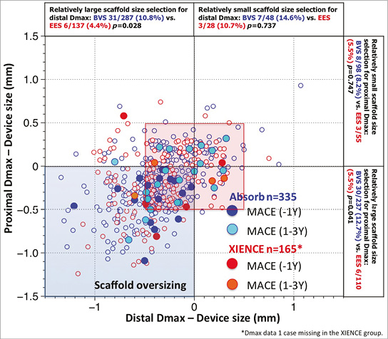
Figure 2. Major adverse cardiac events (MACE) in the first year and at one to three years as a function of mismatch between device and vessel size. During the first year of follow-up of ABSORB II, MACE occurred exclusively in patients/lesions (dark blue filled circles) in which the scaffold was oversized with respect to the vessel diameter (nominal size of the scaffold larger than both Dmax proximal and distal, left lower quadrant). Over the next two years, MACE (light blue filled circles), including six scaffold thromboses causing STEMI and TLR, were no longer clustered exclusively in the quadrant corresponding to scaffold oversizing, but the late MACE events at three years were distributed in the four quadrants and situated, for the most part, in the red frame defining lesions that had received a nominal size scaffold within the range of 0.5 mm with respect to the proximal and distal Dmax27. Prox Dmax: maximal diameter proximal to the lesion; Distal Dmax: maximal diameter distal to the lesion.
Design and unique features of the ABSORB II trial
The design of the ABSORB II trial evolved between August and November 2010 and was finalised in early 201118. One of the major challenges in the design of the trial was the deliberate decision by corporation not to use intravascular imaging for the sizing of the device and for the guidance of the scaffold implantation in order to avoid, in the regulatory post-marketing approval, a labelling involving the use of intravascular imaging29. Another major issue was to power the trial according to the scientific facts established at that time. The vasomotion of a bioresorbable scaffold at three years was apparently a reliable primary superiority endpoint according to the existing literature – showing no vasomotion in metallic stents30-33 – and late loss measured after maximal vasodilatation was considered to be an achievable secondary non-inferiority endpoint. It turned out that comparable vasomotion was observed in the metallic drug-eluting stent and that the late loss in the Absorb BRS was significantly larger than in the XIENCE stent1. The cumulative distribution frequency curve of mean luminal diameter in the XIENCE stent clearly indicated a statistically significant change in vasodilatation comparable to the Absorb in the ABSORB II trial and in the ABSORB Japan trial1,2. How did that come about? In the metallic XIENCE platform, the circular rings connected by longitudinal links are separated by a distance of 1,600 μm. The resolution of current fluoroscopic equipment is about 200 μm and, with the use of that imaging modality, the inward or outward motion of the vessel wall post-nitrate was documented to be 50-70 μm19-21. It is hypothesised that during vasoconstriction the vessel wall prolapses into the lumen and vice versa, while during vasodilatation the vessel wall billows outwards between the rings of the XIENCE stent (Figure 3).
Figure 3. Potential mechanism of vessel wall dilation in vessel stented with a metallic device. The cartoon illustrates the potential mechanism of vessel dilatation in vessels stented with metallic devices. Hypothetically, the vessel wall could prolapse or billow between the two fixed rings of the XIENCE platform, which are separated from each other by a distance of 1,600 microns. The cumulative frequency curve of mean luminal diameter in XIENCE indicated a statistically significant change, demonstrating vasodilation of the stented vessel that was detected by angiography despite its poor resolution (220 microns)1,2. The top panel shows a longitudinal ultrafast pullback acquired with the Heartbeat OCT technology in a vessel scaffolded with Absorb. The inter-ring distance in the Absorb scaffold is 900 microns, whereas the Heartbeat OCT technology has a longitudinal resolution of 18 microns (100 mm/s, 5,600 frames per second)66,67. The prolapse of the vessel wall between the struts is evident.
Did the result of the randomised ABSORB trial differ from the first-in-man (FIM)?
The event rates observed in the FIM were considered as acceptable in the absence of comparators. However, in the randomised trial, it turned out that the event rates were inferior to the comparator. In particular, the six definite very late scaffold thromboses resulting in STEMI and TLR were perceived as a safety warning signal. These cases, combined with the four cases observed in the ABSORB Japan trial, are today at the core of the debate1,2,4,34,35.
Are the three-year outcomes the result of inadequate scaffold selection, expansion or deployment?
Are these events the late sequelae of an inappropriate technique of implantation or the expression of an inherent weakness of the technology when the critical moment of scaffold dismantling – known as late structural discontinuity – occurred. In the FIM trial, signs of late discontinuity (overhanging struts, stacked struts, prolapsing struts, intraluminal isolated struts, covered or uncovered) were observed in 20% of the cases at one year and in 40% at three years. In this ABSORB cohort B study of serial observations on late structural discontinuity36, the authors wanted to be reassuring in their conclusion: “late discontinuity is observed in one fifth of patients in whom at the time of follow-up the struts are fully covered or embedded in tissue and should be viewed as serendipitous OCT findings of a normal bioresorption process without clinical implication”36.
However, four observations of very late definite scaffold thrombosis well documented by OCT, histological and spectroscopic examination of the thrombotic material retrieved by thrombectomy had already raised concerns even before the two-year report of the ABSORB Japan trial and the three-year report of the ABSORB II trial37.
Beyond 730 days, the “polymeric struts” are progressively replaced by a malleable structure (“biological strut” still translucent on OCT) made of proteoglycan – potentially thrombogenic38 – that is subjected to systolic/diastolic strain with a heart cycle frequency of approximately 110,000 beats per day39. It can be imagined that poorly embedded and/or poorly covered “biologic struts” become disrupted or even protrude into the lumen. That catastrophic scenario can only be surmised and remains difficult to demonstrate conclusively (Figure 4)2,35,37. Between three and five years, connective tissues surrounding struts slowly invade the strut voids initially occupied by the polymer, and by then replaced by proteoglycan: this is a critical step in the biointegration of the device into the vessel wall8,40,41 (Figure 5). That final biological step might be an indispensable prerequisite for the biological stability of the treated vessel and the “clinical stability” of the patient.
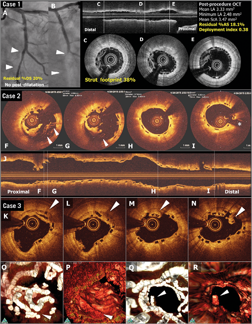
Figure 4. OCT images of scaffold thrombosis and late discontinuities. Case 1. A case of subacute ST (A-E). A patient received a 2.5 mm Absorb BRS in a left circumflex coronary artery without post-dilatation (A). Post-procedural optical frequency domain imaging (C-E) showed severe underexpansion of the proximal part of the scaffold with a minimum lumen area of 2.48 mm2 and a mean scaffold area of 3.47 mm2 with a high density of polymeric struts (D & E). On day four, the patient developed subacute ScT (B). Case 2. OCT images at the time of VLST on day 494 (F-J). OCT after thrombus aspiration demonstrated overhanging struts and uncovered malapposed struts (F & G). The middle and distal part of the scaffold showed no remarkable findings (H & I). Case 3. A case of late strut discontinuities without any clinical sequel (K-R). OCT at two years demonstrated covered and overhanging struts (arrowheads in K, L and M) and malapposed and overhanging struts with tissue bridge behind (arrowhead in N), indicating late discontinuities. In the corresponding three-dimensional OCT reconstructions with (O and Q) or without tissue enhancement (P and R), two rings were overlapping with tissue coverage. One ring was protruding into the lumen from the vessel wall but this was connected to the vessel wall by tissue bridge behind the struts (Q). Modified from Onuma et al with permission2.
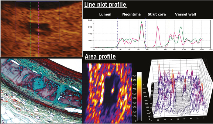
Figure 5. Two-dimensional and three-dimensional presentations of light intensity of the strut core40. OCT images three years after implantation of an Absorb scaffold were analysed by means of light intensity (left upper panel). Inside the translucent core strut region, there was a spot of high light reflection. In the upper panel a pink dotted line passes through this spot. The green dotted line crosses the strut core without passing through the high-intensity spot. The right upper panel is a line plot profile depicting the light intensity along the green and pink dotted lines figuring in the left upper panel. The lower right panel shows colour code mapping and three-dimensional representation of light intensity of the strut core. These OCT images correspond to the early cellularisation by connective tissue of the polymeric strut void occupied at three years by a provisional matrix of proteoglycan (lower left panel)40,41.
The real question today is whether these late events (including very late scaffold thrombosis and some late target vessel revascularisations) could be the late biologic sequelae of an early imperfect technique of implantation coupled with an inappropriate case selection, be it an inappropriate lesion (e.g., thin cap with necrotic core or highly calcified plaque) or even patient (e.g., with high LDL) … or whether these events are the consequence of the late mechanical dismantling of the scaffold35,37,42.
Could late events beyond 730 days be prevented by specific techniques of implantation? The PSP strategy
First of all, it should be stressed that no randomised trial has been completed with specific predefined mandatory techniques of implantation relying on the PSP concept, preparation, sizing and post-dilatation43. Puricel et al have implemented in their routine practice a specific technique of implantation43: i) predilation with a non-compliant balloon up to the same size as the reference vessel diameter (RVD); ii) BRS implantation only in case of full expansion of the non-compliant coronary angioplasty balloon as demonstrated by angiography in two orthogonal planes; iii) implantation of a BRS of the same size as the RVD at 10 to 12 atm; iv) post-dilation with non-compliant balloons up to a maximum of 0.5 mm larger at 14 to 16 atm. By implementing this specific technique, they have reduced the scaffold thrombosis (ScT) rate from 3.3% to 1.0% at one year, and the long-term results are eagerly expected.
The currently available retrospectively collected data, analysed post hoc, acquired in a single-arm approach, document an improvement in outcome at one year only. Today, a long-term prospective randomised trial may not be conceivable or doable for obvious ethical reasons5.
Historically, the randomised ABSORB II trial required a pre-device balloon dilatation with a balloon size 0.5 mm smaller than the reference diameter. However, in this trial the size of the device was selected according to the Dmax algorithm18. Post-dilatation was left to the discretion of the operator, but the “expected” and QCA-measured balloon diameters were prospectively recorded27. The use of a non-compliant balloon was recommended at a quarter mm larger than the nominal diameter of the scaffold, but no specific pressure was mentioned in the protocol.
Secondly, there is an ongoing debate about what the concept of PSP entails. The strategy currently advocated is undoubtedly an evolving concept with multiple variations on the same theme (Puricel et al, Tanaka et al, Tamburino et al, PSP 1, 2 & 3 in GHOST-EU)24,43-45. We have to bear in mind the teleological and therapeutic goals of this technical approach. The ultimate goal may sound abstract and theoretical, but it has a name: shear stress. Shear stress and the normalisation of shear stress should be the criteria for an optimal implantation: no malapposition, no intraluminal protrusion of the strut disturbing the laminar flow, no step-down at the entrance of the scaffold and no step-up at the exit (in other words, perfect embedment of the struts into the vessel wall), no eccentricity or asymmetry of the scaffolded vessel and a device artery ratio between 1 and 1.1 (Figure 6, Figure 7, Moving image 1)46. As a matter of fact, only one intravascular imaging tool can evaluate the above-mentioned criteria for an optimal implantation45,46. Only OCT, with its 20 micron resolution, can scrutinise the vessel and its interaction with the scaffold to the required precision.
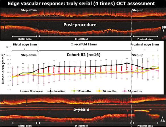
Figure 6. Change in lumen area of both edges and in the scaffold up to five years. Mean values of the lumen area of the target segment with every 1 mm analysis. Lumen area of the entire scaffold segment as well as the proximal and distal 5 mm edges is presented. The four time points (post-procedure, 12, 36 and 60 months) are illustrated by lines of different colours. On average, in the first-in-man B2 cohort, the expansion of the scaffold segment was optimal (expansion index of approximately 1.04±0.20 and area stenosis of −3.80±19.95%)46. The physiological continuity of the lumen contour is restored at medium and long term.
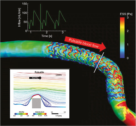
Figure 7. Pulsatile shear stress following scaffold implantation. Shear stress in a human coronary artery scaffolded with the Absorb BRS. Moving image 1 demonstrates the pulsatile shear stress simulations of the same case throughout a cardiac cycle. To calculate the computational fluid dynamics, angiography has been fused with OCT. Shear stress was computed assuming pulsatile flow and non-Newtonian fluid to depict the shear stress in systole and diastole. A colour barcode depicts the shear stress values in pascal (Pa) units. In early systole, the scaffolded coronary artery is almost uniformly blue due to very low shear stress. Conversely, in early diastole at the time of high flow velocity, the scaffolded area is globally red with a shear stress around 3 Pa. It should be noted that the struts of the Absorb platform are easily recognisable on this video and it should also be emphasised that in diastole there is high shear stress (red) on top of the struts and low shear stress (blue) distal and proximal to the struts with signs of reversal of the flow at the foot of the struts, as demonstrated by the local streamlines shown in the excerpt (upper right panel in Moving image 1). The reversed flow could be the nidus for platelet aggregation in a traumatised and de-endothelialised vessel wall post implantation. In Moving image 1, the two lower panels show colour-coded fly-through views of the baseline situation (lower left panel) immediately after implantation and five years later (lower right panel). Initially, the corrugated appearance of the endoluminal surface is evident with the presence of indigo colour on the top of the struts and dark blue colour at the bottom of the struts in regions of very low shear stress. At five-year follow-up, the corrugated appearance due to the strut protrusion has disappeared and regions of low shear stress in dark blue are almost non-existent in the scaffolded area which is, on the contrary, characterised by an alternation of green and red colour which corresponds to a more physiological shear stress (1-3 Pa)68. Modified illustration reproduced with permission of JACC Cardiovasc Interv68.
In an ideal world, OCT should be performed prior to any treatment if possible, or at least after the initial preparation in order to evaluate the calcification of the vessel, its eccentricity, its size, etc. All the possible techniques of lumen enlargement, such as ballooning, scoring, cutting, and debulking, that are available in our armamentarium should be applied so that the scaffold is used only for its scaffolding capability and not abused for its weak dilating, expanding radial force47,48. The circularity of the vessel lumen after preparation will guarantee the circularity of the scaffolded vessel after implantation. The circular circumference of the scaffolded segment should be in strict physiological continuity with the proximal and distal reference areas. A non-conformity index software has recently been designed that may account accurately for the proposed strategic procedural approach. It is a composite imaging endpoint that integrates eccentricity, asymmetry, overexpansion, underexpansion, and tapering in a comprehensive way and helps us to monitor the quality of an implantation (Figure 8).
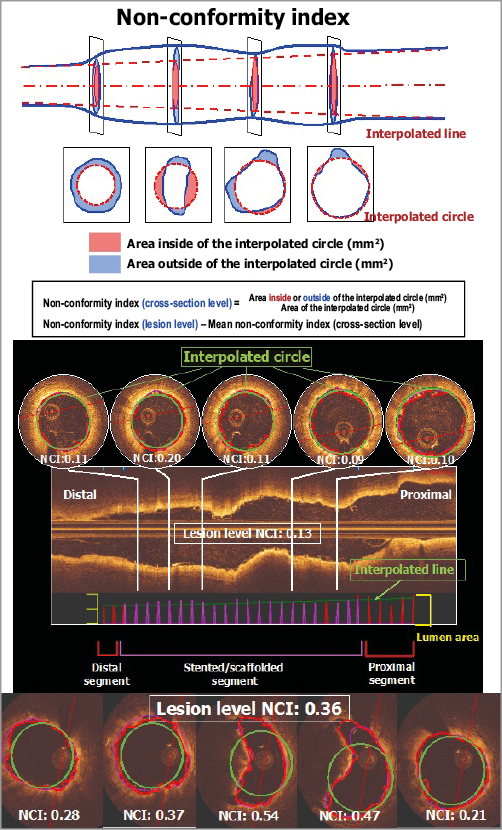
Figure 8. Description of the non-conformity parameter. The optimal configuration of an implanted scaffold should follow the naturally tapered circular tube interpolated between the “non-diseased” reference areas proximal and distal to the scaffolded area. The non-conformity index (NCI) quantifies the degree and extent of geometric deviations from the optimal interpolated tube. For each cross-section of the OCT pullback, we calculate the areas deviating (inward and outward) from optimal interpolated circles using their centres of gravity which are aligned with the centreline of the two reference areas, proximal and distal. A dedicated software has been designed for calculating the NCI (QCV-CMS software, version 4.69; Leiden University Medical Center, Leiden, the Netherlands). The non-conformity index ranges from 0 (perfectly conformed) to 1.
Ideally, post-scaffold OCT should demonstrate whether a perfectly sized non-compliant balloon inflated at high pressure has further embedded the struts, although the tissue composition of the vessel wall (fibrotic, calcified) may definitely preclude profound embedment of the larger footprint of the thick Absorb struts49-51 (Figure 9).
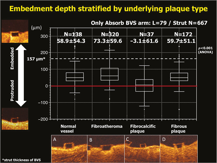
Figure 9. Correlation between embedment depth and plaque morphology. Embedment depth has been assessed according to different plaque morphologies: normal vessel (A), fibroatheroma (B), fibrocalcific plaque (C), and fibrous plaque (D). The best embedment is observed in fibroatheroma. Data are shown as box-and-whisker plots and mean±standard deviation50,51.
The large footprint of the Absorb – scaffold area covers 26% to 32% of the vessel wall area– may in itself hinder the penetration of the struts into the vessel wall. When measured with OCT, the width of the Absorb struts at the hinge point can be as large as 800 microns (Figure 10)51,52. The width of the strut could also influence the embedment of the strut: according to the simple principle “pressure=force/area”, the same force applied to an intraluminal device with a larger contact area would generate a lower pressure to the vessel wall than a device with a smaller contact area. This is basically the rationale for a more aggressive post-dilatation with non-compliant and high-pressure balloons, the third component of the PSP strategy.
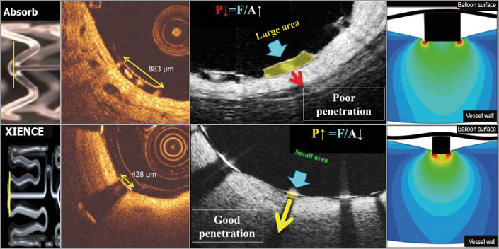
Figure 10. Footprint of the strut and embedment. The upper row represents OCT cross-sections of the Absorb BRS scaffold while the lower row depicts the cross-section of the XIENCE stent. The vertical lines (yellow) superimposed on both devices in the left side panel correspond to OCT cross-sections at ψ-hinge (psi-hinge) level. The ψ-hinges are the distal part of a longitudinal connector, where the angle between the connector and the W-shaped ring is acute51. The ψ-hinge strut width (yellow two-sided arrows) of the Absorb scaffold can reach up to 883 µm while the strut width of the XIENCE stent is only 428 µm. When the same balloon pressure is applied to the large footprint of Absorb and the small footprint of a metallic strut (middle, lower row), the metallic strut (like an ice-skate in snow) can be embedded and expanded by the dilating balloon much better than with the Absorb device (like a snowshoe in snow)51.
However, in the end, it has to be stressed that the main mechanical determinant of scaffold deployment and expansion is primarily volumetric and not barometric, and there is no such thing as a “magic” value of atmospheric pressure (15,16,17 atm) for balloon inflation. Sixteen atmospheres is part of a pragmatic recipe that could only be scientifically substantiated by an appropriate but retrospective statistical analysis (e.g., C-statistics) of the optimal inflation pressure used in patients with events vs. patients without events, in the randomised trials conducted up until now (ABSORB II, ABSORB Japan, ABSORB China, ABSORB III and ABSORB IV). In other words, only a PSP strategy guided by OCT could be effective in improving the short- and potentially long-term outcome. Whether applying a “blind” PSP strategy could be as efficient as an OCT-guided PSP remains to be demonstrated.
As far as the ABSORB II trial is concerned, although the quality of data acquisition is indisputable, even in-depth analysis of the small number of events did not resolve the question whether a late event can still be the result of an inappropriate technique of implantation or whether the unavoidable dismantling of the scaffold carries an inherent risk of very late scaffold thrombosis. These two hypotheses are currently neither dismissed nor confirmed.
The in-depth univariate analysis of the six very late scaffold thromboses has potentially identified one IVUS parameter, i.e., the expansion index <0.6 (p<0.001), that is suspected of being involved in the late occurrence of a sudden scaffold thrombosis.
We have to consider that, during this long period of latency prior to the occurrence of late events, many major remodelling processes occur that should have theoretically improved the initial imperfections of an inadequate technique of implantation: initial eccentricity and asymmetry regress, struts with malapposition up to 359 microns become reconnected with the vessel wall, minimal lumen area gets relocated and struts jailing the side branch disappear, while mean lumen area increases (Figure 11)49,53. These are all dynamic signs of remodelling that can actively compensate for the initially inadequate technique of implantation (Figure 11).
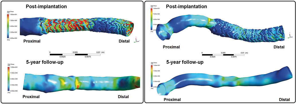
Figure 11. Post-procedural shear stress in underexpanded and overexpanded scaffold and its long-term evolution (at five years). The wall shear stress simulations in a case of an underexpanded (left) and overexpanded scaffold (right), combining three-dimensional angiography and optical coherence tomography. In the case of underexpansion (left), post-implantation lumen showed a step down and step up at the proximal and distal edges of the bioresorbable scaffold. The proximal underexpanded part of the device causes relatively high shear stress of >5 Pa on top of the proximal struts, whereas the part of the scaffold normally expanded exhibits low shear stress of 0.5-1.0 Pa between the struts. The high shear stress initially observed in the proximal part of the scaffold was, at five years, no longer present as a result of dynamic remodelling and lumen enlargement. In the overexpanded scaffold case (right), the inter-strut shear stress was very low (<1 Pa). At five years, the very low shear stress was no longer observed69. In both cases at five years, the lumen exhibited a smooth endoluminal surface, and accordingly the shear stress distribution became more homogenous and physiological56,70,71. Pa: pascal unit of shear stress.
In addition, we have not yet fully investigated the other multifactorial determinants of interaction between the scaffold and the vessel wall, such as shear stress in the scaffolded vessel, wall stress/strain relationship generated by the scaffold, the tissue composition of the vessel wall underlying the scaffolded vessel and all the biological factors promoting the coverage of the struts54,55.
Current research on remodelling (“Glagovian appraisal of the ABSORB II trial”) following Absorb implantation suggests that long-term expansive remodelling might be triggered by the initial barotrauma quantified by the expected balloon artery ratio larger than 1.25. In other words, the effect of a PSP strategy on late remodelling and lumen enlargement may thus possibly have some scientific foundation, and the long-term benefit of a PSP strategy might be less simplistic than at first glance. Full elucidation of the effect of a PSP strategy will require complex, long-lasting and prospective studies.
What is certain is that the three actors in the current polemics will improve with time. There will be new devices made of PLLA processed differently or polymer other than PLLA that will provide stronger, thinner and circular struts that will be easier to embed and that will be bioresorbed in optimal duration and more quickly covered by new tissue56.
The optimal duration of the bioresorption process (ranging from three to 42 months depending on the polymer) is also a biological enigma that has to be resolved by “trial and error” in preclinical and clinical studies41,57-59. Proper selection of patients and lesions could also contribute to long-term results. For instance, in the TROFI II randomised trial, the MLD post procedure (2.46 mm) was identical in both arms conducted in STEMI patients whose thrombotic lesions could be more amenable to scaffold treatment60,61. From that point of view, all-comers trials such as AIDA or COMPARE perhaps involved premature trial design approaches; a dedicated randomised trial performed in a selective, well-defined group of patients (e.g., CTO or STEMI) might have been more relevant for a good understanding of the specific clinical indication of this new technology. Duration and type of antiplatelet therapy are and will be a hot topic in the years to come, another issue that is beyond the scope of this article.
Finally, operator experience –with or without the discipline of a PSP strategy, with or without the guidance of OCT– will impact on the short-term and long-term results of the BRS technology. This was the case with the BMS and drug-eluting stent in the SCAAR registry that initially reported an excess of mortality and myocardial infarction with the drug-eluting stent in the early phase of recruitment, whereas the outcome was reversed in favour of drug-eluting stents when the operators became more experienced62-64.
Recently, a well-advised and experienced trialist stated judiciously that it could take a decade of research to figure out the answers to all these questions … a case of “déjà vu” with drug-eluting stents65.
Conflict of interest statement
P W. Serruys and Y. Onuma are both members of the international advisory board for Abbott.
Supplementary data
Moving Image 1. Pulsatile shear stress following scaffold implantation.
Supplementary data
To read the full content of this article, please download the PDF.
Pulsatile shear stress following scaffold implantation.